hustle domain was triggered too early. This is usually an indicator for some code in the plugin or theme running too early. Translations should be loaded at the init action or later. Please see Debugging in WordPress for more information. (This message was added in version 6.7.0.) in /wordpress/wp-includes/functions.php on line 6114
Notice: Function _load_textdomain_just_in_time was called incorrectly. Translation loading for the rocket domain was triggered too early. This is usually an indicator for some code in the plugin or theme running too early. Translations should be loaded at the init action or later. Please see Debugging in WordPress for more information. (This message was added in version 6.7.0.) in /wordpress/wp-includes/functions.php on line 6114
Notice: Function _load_textdomain_just_in_time was called incorrectly. Translation loading for the wordpress-seo domain was triggered too early. This is usually an indicator for some code in the plugin or theme running too early. Translations should be loaded at the init action or later. Please see Debugging in WordPress for more information. (This message was added in version 6.7.0.) in /wordpress/wp-includes/functions.php on line 6114
Warning: count(): Parameter must be an array or an object that implements Countable in /www/wp-content/plugins/wpo/inc/propaganda3/wpo/MetaBase.php on line 23
Warning: count(): Parameter must be an array or an object that implements Countable in /www/wp-content/plugins/wpo/inc/propaganda3/wpo/MetaBase.php on line 23
Warning: count(): Parameter must be an array or an object that implements Countable in /www/wp-content/plugins/wpo/inc/propaganda3/wpo/MetaBase.php on line 23
Warning: count(): Parameter must be an array or an object that implements Countable in /www/wp-content/plugins/wpo/inc/propaganda3/wpo/MetaBase.php on line 23
Warning: count(): Parameter must be an array or an object that implements Countable in /www/wp-content/plugins/wpo/inc/propaganda3/wpo/MetaBase.php on line 23
We did an article on trouble shooting dilute phase pneumatic conveying systems a while back, so we wanted to follow it up with the same for dense phase. There are a few main differences between a dilute phase pneumatic conveying system and a dense phase pneumatic conveying system. Dilute phase typically moves the product in a “continuous” flow method, operates with more velocity, and handles products that are less likely to be damaged during transfer. Dense phase pneumatic conveying systems move the product in a “slug” flow, conveys product at a much lower velocity, and is best suited for friable or abrasive products. If you’d like more information on the differences between the two check out this article: Dilute vs Dense Phase Conveying.
To begin, every dense phase conveying system will have these four main components: An Air Compressor, Convey Lines, Filter Receiver, and an ASME Code Pressure Vessel also referred to as Dense Phase Pot (DPP) or Dense Phase Transmitter (DPT). We will take a look at each component, define its purpose in the system, discuss the potential issues each has and what to look for in your systems operation to detect the problems.
Air Compressors
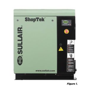
The air compressor is the “power source” for the system. They tend to fall into two categories at a facility; they are either dedicated to the sole use of the dense phase system or they are part of the overall plant air system. Regardless, there are a few parts to them that can cause some costly issues.
Common Issues with Air and Water Separators
Convey Lines / Elbows / Diverters
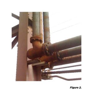
The biggest difference from a dilute phase system in relationship to the convey lines is, dense phase systems typically utilize thicker wall pipe (Sch. 40 or Sch. 80) and the couplings are Victaulic grooved couplings vs compression style. Elbow support in either type of pneumatic conveying system is important but in a dense phase system it is mandatory. The slugs of product that come down the convey line have a great deal of mass and if the elbow is not supported correctly you will blow the elbow right off the line.
Like elbows, the slugs of product can have similar effects to diverter valves depending on the design of the valve. (Insert shameless plug) Our hose style 2-Way slide diverter design allows the product to flow directly through each convey line without coming in contact with a side wall to be diverted between lines.
Filter Receivers and Bin Vents
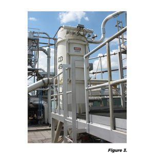
There are no design differences in a filter receiver for a dilute phase system vs. a dense phase system. The difference comes in being able to identify a problem. In a dense phase conveying system, there are three different air flows that come through it depending on what process is happening within the dense phase cycle.
The discharge pressure readings on a bin vent are difficult to diagnose any issues due to the change in airflow, and difficult to have any alarm set points.
Dense Phase Transmitter / Dene Phase Pot / Dense Phase Pressure Vessel (DPT)
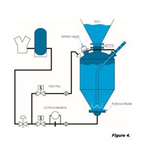
There are two design types either you have a top discharge style or a bottom discharge style. This is decided by the material that is being conveyed in the dense phase system. The top discharge style is great for fluidizable materials such as Talc. The bottom discharge design is great for permeable materials such as plastic pellets. (See Figure 4)
Top Discharge Design
Bottom Discharge Design
Air Management
Depending on the manufacture of the dense phase system you will get different philosophies on how the airflow is managed. They typically fall into two categories: either you keep the CFM constant, or you keep the PSIG constant.
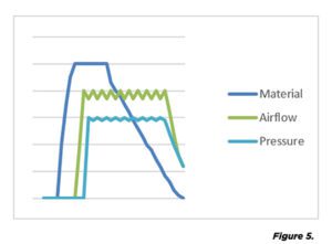
When a dense phase system is correctly applied and operating efficiently you will begin filling up the vessel. As the high level sensor trips and the system airflow kicks on and starts to convey material down the line then system pressure rises in the system. When all is working correctly the material will gradually go out of the vessel and the airflow and pressure will stay constant through the entire cycle. (See Figure 5)
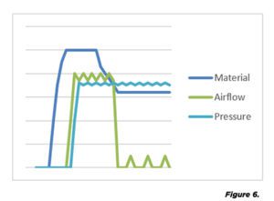
When a convey line plugs you will see the following in the airflow of the system: The vessel is filling up with material, the airflow rises, the pressure in the system comes up, as material is conveying, it plugs then all the sudden there is no more material coming out. The airflow will drop off, but the pressure will stay constant. (See Figure 6.)
The Material
The last place to look for any conveying issues is your material. For dense phase systems to work correctly the material must be consistent. They will not work well if you have different particle sizes. If you have a process ahead of the dense phase transfer system where some fines may be getting mixed in with your uniform material size, it will cause plugging.
This is a 30,000 ft view of typical issues you may see or can look for. If you have a specific application you are dealing with issues on, please feel free to contact us and we would be happy to discuss your system in detail.
Related Post
Customized Nuisance Dust Collection and Control in Pneumatic Conveying Systems
11 Pneumatic System Considerations for the Chemical Industry
Choosing the Right Bulk Bag Filling Equipment in the Chemical Industry
Using Robotics to Overcome Manual Palletizing System Challenges